


 The Right Approach: I Hear the Train A Comin'
 It’s Only Common Sense: OCCAM—the Time Is Now
 Marcy's Musings: The Growing Industry
HDPUG Demonstrates Benefits of Cooperative R&D
June 8, 2015 | Pete Starkey, I-Connect007Estimated reading time: 17 minutes

Feeling very privileged to be invited to attend the open presentations day of the annual European meeting of the High Density Packaging User Group (HDPUG), I travelled to Royal Leamington Spa in Warwickshire, UK, on May 27 with guest speaker Michael Weinhold, Technical Director of the European Institute of Printed Circuits (EIPC).
The High Density Packaging User Group (HDPUG) is a member-driven, non-profit, project-oriented industry consortium that addresses the integration of new electronics component packaging and interconnection technologies into the supply chains of its member companies. Its stated mission is to reduce the costs and risks for the electronics industries when utilising high-density electronic packaging, and it achieves its objective by promoting the concept of cooperative R&D – sharing scarce resources and expertise to address issues of common interest, to enable major problems and global technical issues to be resolved in a fraction of the time and at a fraction of the cost it would take for individual companies to do it alone.
HDPUG holds four two-day member meetings each year, two in the United States, one in Europe, and one in Asia. The first day is devoted to public-domain project presentations, with non-members attending by invitation, and members-only discussions take place on the second day.
HDPUG Executive Director Marshall Andrews opened this year's European meeting, welcomed members and guests, stated the ground rules: "We do not discuss IP and we do not discuss price," and introduced Martin Cotton, Director of OEM Marketing at Ventec, who had sponsored the event.
Cotton echoed Andrews' welcome and gave a brief history of the evolution of Ventec as a leading supplier of high-performance PCB substrates and its commitment to providing ultra-clean materials in thicknesses as low as 25 microns for HDI applications. Speaking from his many years' experience as a designer, he cautioned against over-specifying material and carrying the cost of performance overshoot. It was not uncommon for designers to specify the highest-performance – and consequently highest-cost – material for an application where its use was not technically justified, rather than put effort into the design exercise.
Cotton questioned whether designers really understood the significance of material properties other than electrical, and explained Ventec’s policy of rationalising their data sheets to clarify physical properties and actual constructions, and his personal role in working with OEM designers to help them to choose and specify the most appropriate and cost-effective solution.
HDPUG project facilitator John Davignon chaired the project-review session, which began with a Phase 2 status update on the Optical Interconnection project, presented by Marika Immonen from TTM in Finland, and Richard Pitwon from Seagate Technology in the UK. The project had begun five years previously with the objective of evaluating the feasibility and maturity of optical waveguide based technologies on PCBs, determining performance benefits and limitations using polymer waveguides and fibres for 1-2m links. The focus was on optical fibre and waveguide link characteristics, practical connectivity options and end-to-end link implementations. The project was now at Phase 2; Richard Pitwon described the test vehicle used as a complete system-level demonstrator platform, consisting of a backplane with pluggable daughter cards and mezzanine cards with 28Gbps connectors, for testing flexible and embedded waveguides. High speed 28Gbps test data could be driven across the platform from an external data source or from a pluggable logic card. The project team was currently working with Fraunhofer Institute to study glass waveguides, which had lower loss characteristics at longer wavelengths.
Through-silicon-via specialist Dave Love, HDPUG facilitator for TSV packaging, gave updates on the TSV Signal Integrity and TSV Board Level Reliability projects, in a context of current debate about the potential improvements in power and signal integrity to be gained by 2.5D packaging compared with traditional package-on-printed-circuit-board technology. The objective of the Signal Integrity project goal was to measure of differences. The project was at the definition phase: technical choices had been made on device-under-test and methods to compare signal launches for devices mounted on TSV interposer through the PCB to devices mounted on interposer on the same PCB with devices mounted in traditional packages through the PCB to devices mounted in traditional packages on the same PCB. The project was open to available samples and critical mass was needed to move it forward. The Board Level Reliability project recognised the lack of industry data on board-level reliability for 2.5D packaging, particularly in temperature cycling for high end computer and network applications, and drop and mechanical shock performance in mobile applications. Package suppliers typically focused on package-level qualifications, and 2.5D devices had weak structures susceptible to damage from strains imposed by being soldered to a PCB. The project presented the opportunity to quantify the risk by collaborative research and to publish the findings. A by-product would be characterisation of SMT assembly and the publication of a guideline document.
High speed press fit connectors with fragile, small-diameter pins on dense pitches and with tight tolerances, can be easily damaged during insertion and require rework. HDPUG facilitator Jack Fisher was joined by project leader Lars Bruno from Ericsson calling-in, to give an update on the Press Fit Rework project. The project objective was to determine and document the effect of rework on press fit connection strength, hole wall deformation and gas-tightness for new high-speed press fit connectors, using standard DIN connectors as a point of reference. The experimental plan was to perform a series of insertion and removal operations on a range of four high-speed back-plane connectors on two sets of eight PCBs, made on a standard base material, finished in either ENIG or immersion tin, with hole sizes at nominal, maximum tolerance and minimum tolerance, and study the results by microsectioning in horizontal and vertical axes. The biggest challenge anticipated was in achieving the critical hole diameters required for meaningful measurement in the light of normal drill-diameter and drilling machine process tolerances. The results were due to be published as a report in Q1 2016, indicating which pin and design combinations would best withstand rework, and what could be expected in terms of strength and hole wall deformation.Page 1 of 4
Share on:


Suggested Items
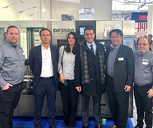
Taiyo Circuit Automation Installs New DP3500 into Fuba Printed Circuits, Tunisia
04/25/2024 | Taiyo Circuit AutomationTaiyo Circuit Automation is proud to be partnered with Fuba Printed Circuits, Tunisia part of the OneTech Group of companies, a leading printed circuit board manufacturer based out of Bizerte, Tunisia, on their first installation of Taiyo Circuit Automation DP3500 coater.
Vicor Power Orders Hentec Industries/RPS Automation Pulsar Solderability Testing System
04/24/2024 | Hentec Industries/RPS AutomationHentec Industries/RPS Automation, a leading manufacturer of selective soldering, lead tinning and solderability test equipment, is pleased to announce that Vicor Power has finalized the purchase of a Pulsar solderability testing system.
AIM Solder’s Dillon Zhu to Present on Ultraminiature Soldering at SMTA China East
04/22/2024 | AIMAIM Solder, a leading global manufacturer of solder assembly materials for the electronics industry, is pleased to announce that Dillon Zhu will present on the topic: Ultraminiature Soldering: Techniques, Technologies, and Standards at SMTA China East. This event is being held at the Shanghai World Expo Exhibition & Convention Center from April 24-25.
AIM to Highlight NC259FPA Ultrafine No Clean Solder Paste at SMTA Wisconsin Expo & Tech Forum
04/18/2024 | AIMAIM Solder, a leading global manufacturer of solder assembly materials for the electronics industry, is pleased to announce its participation in the upcoming SMTA Wisconsin Expo & Tech Forum taking place on May 7 at the Four Points by Sheraton | Milwaukee Airport, in Milwaukee, Wisconsin.
Hentec/RPS Publishes an Essential Guide to Selective Soldering Processing Tech Paper
04/17/2024 | Hentec Industries/RPS AutomationHentec Industries/RPS Automation, a leading manufacturer of selective soldering, lead tinning and solderability test equipment, announces that it has published a technical paper describing the critical process parameters that need to be optimized to ensure optimal results and guarantee the utmost in end-product quality.